Performance Exhaust Systems
Turbo Manifold Design: Runners, Collectors and CNC Flanges
Three design decisions that decide whether a turbo manifold works: where the runners go, how they merge, and how it bolts up.
Published 2026-11-03
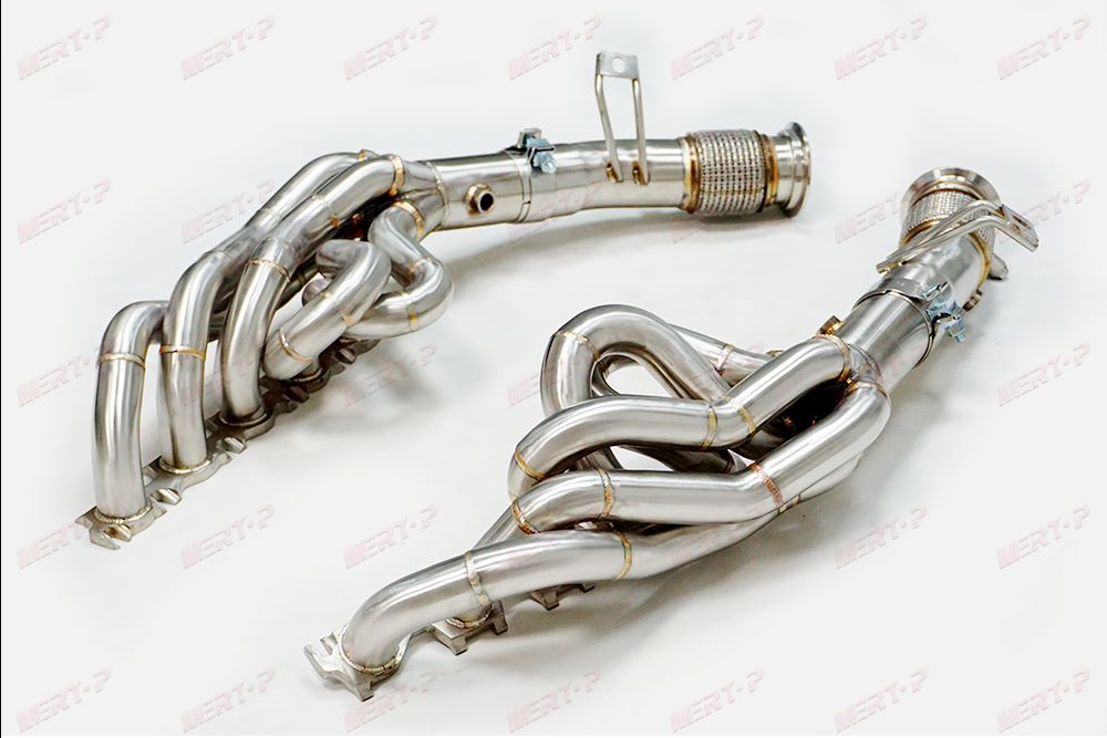
A turbo manifold is a junction with a job description: collect the exhaust from every cylinder, deliver it to one turbocharger, hold that turbocharger in a precise position against the cylinder head, and keep doing it through heat cycles that would punish lesser fabrication. Three design decisions dominate the work — runner routing, the collector, and the flanges — seen from the perspective of the workshop that builds them in steam-pipe SS304.
The three decisions are not independent, and the post treats them in the order the workshop meets them rather than the order a catalogue lists them. Routing constrains the collector, because the merge has to happen where the runners end up; the collector constrains the flange program, because the turbo's position is set by both; and the flanges, finished last, have to forgive whatever the first two decisions left imperfect. A manifold is a small system of compromises arranged to look inevitable, and reading the decisions in sequence shows where the inevitability is earned.
- Workshop noteWritten from production practice
- Range-anchoredTied to a family in the range
- Process factsAs the work is done
- Fitment firstConfirmed on inquiry
Runners: Routing Is the Design
The runners are the individual tubes from each exhaust port to the collector, and their routing is most of the design. The constraints are physical: the turbo must sit where the engine bay and the downpipe expect it; the runners must reach the collector from ports spread along the head; and the whole assembly must clear the engine, its accessories and the bay itself. On a straight six the ports line up along one bank and the routing is a procession; on other layouts the routing is a negotiation, which is why manifold design starts from a scan of the original part or the engine, never from a blank page.
Steam-pipe construction — thick-wall tube — is the range's answer to the thermal side of the problem. A turbo manifold lives at the highest temperatures in the exhaust system and cycles with every drive; wall thickness is what lets the part treat those cycles as routine. The runners are bent and welded on fixtures that hold the turbo flange in its installed position, so the routing in the design is the routing in the car.
Collectors: Cast, Wire-Cut or Printed
The collector is where the runners merge into the turbo inlet, and this range builds it three ways. Cast collectors serve settled production designs: the merge geometry is cast as one piece, smooth and repeatable. Wire-cut collectors serve tight merges, where the collector's shape is cut rather than formed. Printed tooling serves prototypes and low-volume programs, where the design may still move and the collector needs to move with it cheaply.
The three routes are not a quality ladder; they are a match between a merge geometry and a production stage. A design often travels through them — printed while it settles, cast once it is selling — and the collector the customer receives is the one the design's stage calls for, with the merge itself checked as part of the manifold's dimensional inspection.
Flanges: The Faces That Decide Whether It Seals
A turbo manifold has two sealing faces: the head flange and the turbo flange. Both are machined — the head flange is billet, milled on multi-axis centres to the OEM cylinder-head port profile, and both faces are machined flat after welding, because welding moves metal and a flange that was flat before welding is a rumour by the time the part cools. The head flange's port openings are milled to the OEM cylinder-head profile for the engine — the manifold meets the head on the head's own geometry, not on a generic oval — and the turbo flange is faced to the footprint of the turbo the application runs.
This is the least glamorous and most consequential part of the design. A manifold whose runners are beautiful and whose flanges are warped will leak at both ends, and the leak will be blamed on the design rather than the facing. The production rule follows: the faces are finished last, in the part's welded state, and checked before the manifold is finished and packed.
Heat: The Constraint Behind All Three Decisions
It is worth stating plainly what the three decisions have in common: heat. The manifold is the hottest fabricated part on the car, and it does not merely get hot — it cycles, heating and cooling with every drive, expanding and contracting against two bolted faces that would prefer it didn't. Runner routing decides where the heat concentrates; wall thickness decides how the part carries it; the collector's construction decides whether the merge — the point where every runner's heat arrives together — is the strongest part of the assembly or the weakest.
This is why the finishes conversation for a turbo manifold is a heat conversation: ceramic coating is specified for heat management, shields protect the bay around the manifold, and the burnt or brushed finishes are chosen knowing the part will re-colour itself in service regardless. It is also why the flange faces are machined in the welded state — a part that will move with heat for its whole life should at least start true at room temperature.
Buyers evaluating a manifold design they have been offered — anyone's, not only this range's — can read most of its quality from how seriously it takes the heat: wall that is specified rather than implied, a collector built for the merge rather than gathered into it, flanges finished after welding. The three decisions are, in the end, three ways of taking heat seriously.
There is a fourth, quieter test that follows from the other three: ask how the design was arrived at. A manifold developed from a scan of the original part, on a fixture, through a checked prototype, carries its decisions in a record. A manifold adapted from a photograph carries them in a hope. The parts can look identical in a listing; the records cannot, and the record is what a buyer is really being asked to trust.
From Design to an Orderable Part
A manifold design becomes an orderable part when it has a fixture, a checked prototype and a documented specification — the 2JZ manifold shows what that looks like for one engine, with construction, wall, outlet and fitments all named. Programs ordering manifolds for engines outside the documented list are buying the sequence itself: scan, design, fixture, prototype, check. The design decisions above are the ones the customer will be asked to approve along the way — routing against the bay, collector route against the program's stage, and the flange program against the engine and turbo being joined.
Source the parts behind turbo manifold design
Send your vehicle, engine and item list for a confirmed fitment check and a quotation on the parts covered here.
Send an Inquiry